
Mechanical Questions
Technical questions often asked about the locos in Andrews collection
{slider title="What's the difference between a 4w and an 0-4-0?" title class="blue"} Although the UK locomotive engineering industry regards any 4-wheeled (coupled) loco as an 0-4-0, enthusiasts have over the years tended to amend the wheel arrangement classification for all locos that did NOT have side rods to indicate more accurately the "type" of locomotive it was, much in the same way as they would specify a DM, a DH or a DE. In continental practice, of course, a rigid frame two axle loco would be classed as a "B", and again would not specify whether it was rod-coupled or otherwise.
In the case of Andrew's collection, there are three such locos, and all three utilise roller chains (the same type as used on bicycles or motorbikes, but substantially larger). "Pluto", the Planet diesel mechanical, has its final drive gearbox frame mounted within the cab, and a single "triplex" chain drives the rear axle, the axles then being coupled by a single "duplex" chain. "Charlie" and "Cheedale" are both based on Sentinel practice - "Charlie" with its rear-mounted RF11 is a similar layout to "Pluto", but "Cheedale" has its gearbox in the centre driving each axle in an inverted "vee" form. Thomas Hill and Sentinel used 2.5" pitch duplex chains throughout.
Chain drives were maligned by those manufacturers that did not use them. The short fact is that they provide constant torque, free from the "cyclical" variations that characterise side rod drives, and enable the axles to be freed from the restrictions of horn guides so that they may more readily cope with rough tracks and sharp curves. In fact, the arrangement of mounting the axle boxes on radius arms (and spring leaves simply bearing on the underside of the chassis) is forced on the designer by the need to accommodate the stretch that inevitably occurs as the chains wear; which incidentally means that the wheelbase dimensions quoted for any chain drive loco will be "nominal". Thomas Hill's practice was to recommend that chains be renewed when they had stretched by 3%. Their 2.5" duplex chains had a minimum breaking strain of 190,000lbs, and this was proven (on paper and by repute, in real life) to mean that the chains were stronger in use than the locomotive axles.
The one disadvantage of chain drives is that they are exposed, and in needing lubrication, they become dirty and the locomotives become caked in oily muck anywhere in the 'throwing range' of the chains. The mechanical adjustment of chains for tension was only required occasionally (and much simpler to carry out than certain manufacturers liked you to believe) but although 6w steam and diesel locos were built, the hassle of having to 'double adjust' (i.e. adjusting a chain between axles A and B would result in double the adjustment being required between B and C) means that they were generally avoided.
Of course, a 4w or 6w wheel arrangement may not only be indicative of chain drives. Thomas Hill built over 25 "4w" locos for the UK Ministry of Defence - 19 were chain drive, but the follow-on ones were shaft drive, i.e. each axle has a final drive gearbox and the torque is passed to them by propellor shafts. Shaft drive locos possess the same technical advantages of the smooth drive as with the chain drives, plus the benefits of not requiring adjustment and being much cleaner. Their first cost is of course much higher. For completeness of this review, 6w locomotives in the industry include the Rolls-Royce/Thomas Hill "Steelman" type whereas British Steel (Corus) and the NCB operate(d) 6w diesel-electric locos where each axle has its own traction motor, and mechanical coupling was avoided in the same manner as the bogie of a "Co-Co" mainline loco.
{slider title="Diesel Mechanical v Diesel Hydraulic" title class="blue"} Or, if a loco has a fluid coupling in its transmission, why isn't it a diesel-hydraulic?
This is an interesting question and the answer is simple but then gets "fudged"! In a fluid coupling, an impeller, driven by the engine flywheel, propels oil onto the turbine (connected to the transmission) so the force is, briefly, going through a hydraulic medium. But the physical characteristic of fluid coupling is that it only transmits the same torque/rpm as the engine inputs. Now that is not entirely true, as there are some losses ("heat rejection"), but in essence, the fluid coupling works in the same manner as a dry friction plate clutch. The fluid within the coupling is not under pressure, but woe betides the driver who leaves the loco stationary, in gear with the engine running as a temperature build-up results in the fusible plug melting and throwing all the oil out.
In a torque converter, again, fluid is thrown from an impeller to a turbine but is deflected along the way by static blades within the housing and the fluid is under pressure. The physical design of the various components and the resulting flow creates a very different outcome. Although the engine may input 'x'lb/ft torque at 'y'rpm, the output from the converter will be 'a' lb/ft and 'b' rpm. At stall, for example, the engine may be inputting power at 16-1800rpm, but the converter output will be zero rpm: the torque, however, on a Twin Disc converter, will be around 5.5 times the torque the engine is putting in. Of course, 'you don't get 'owt for nowt' - the converter will get hot and must be cooled. The typical best efficiency on a Twin Disc is about 80% at full power, or put it another way if you put 300hp into the converter, you will get out around 240 to the wheels and 60 as heat.
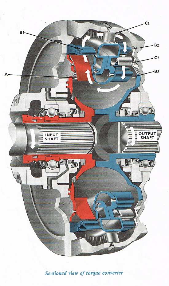
In the above diagram of a Twin Disc converter, oil is flung from the impeller (A) to the first of the turbine blades (B1). Guide vanes (C1) direct the fluid onto the blades of the second turbine (B2), repeated by the second stage guides (C2) and on to the third ring of turbine blades (B3)
So that's the basic difference between a fluid coupling drive and a torque converter - but I said things get fudged. Take a Voith transmission. Clearly a hydraulic, and within its casing, you might find a couple of torque converters (separately filled and emptied and connected by different gearing to the output stage) but also a fluid coupling, which comes in for the upper-speed range to give a direct (well, 1:1 fixed) drive to the wheels. So a fluid coupling can form part of a hydraulic transmission but on its own is regarded as mechanical.
{slider title="What's a final drive?" title class="blue"} Most diesel-hydraulic or mechanical locomotives have transmissions which rotate in one direction, i.e. that of the engine which is 'anti-clockwise viewed on flywheel'. In order to go forwards or backwards, they require a gearbox that can reverse that rotation, and this is generally carried out in a "final drive reversing gearbox" which is either jackshaft or axle-mounted and turns the drive additionally through 90 degrees.
(Some locos do not need reversing final drives - RSH built some locos with Crossley 2-stroke engines where the engine itself was stopped and reversed in order to change direction, in this case, the final drive was just a 90-degree function. Similarly, locos using hydrostatic drives can reverse the hydraulic motors like a diesel-electric traction motor. UK hydrostatics are mostly low hp n.g. types, but larger locos have been built on the continent, and UK examples include the Autoloc and Zephyr locos at Mountsorrel, and the 6-axle Vollert at Tarmac/Lafarge at Tunstead.
Shaft drive locos, such as the R-R/TH "Steelman" employ a non-reversing final drive mounted on each axle. The reversing function is therefore carried out in a transfer box, or in some continental locos in a fully-reversing Voith transmission, where it is possible to use opposite direction converters to create braking force without using friction brakes.
Finally, a lot of 1st generation DMUs use reversing final drives - but because of their higher speed requirement, these are single-stage reduction with ratios around 3:1.
So let's look at the main final drive gearboxes found in industrial and BR shunters..
Self-Changing Gears Ltd, type RF11
SCG, based in Coventry, manufactured a range of transmission products that although expensive, were rugged units of exceptional build quality. The design appeared around the 1940s and continued until SCG's demise in the 1990s, though by then the price of a one-off RF11 was over £20,000.
There were broadly two types. The standard box was jointed in two places on the horizontal, and the 3 shafts (the top shaft, intermediate and output) were in a vertical line. The heavy-duty gearbox (referred to officially as the "Z'ed" but colloquially as a "Bulging Bertie") had the intermediate shaft offset to the rear and the intermediate section of the casing had a domed raised section that covered the gears. In this form, it was rated as suitable for up to 640hp or 60ton or loco weight, the limit being the tooth load resulting from torque or adhesion. Thomas Hills pushed the limit with SCG building a 70ton 0-6-0DH with only 427bhp - SCG accepted it under pressure but it is of academic interest that the loco suffered 2 final drive gear teeth failures during its career.
The RF11 had a number of variations in the casings depending on how the gearbox was being mounted - for example in BR 03 and 04 class locos, the jackshaft output is catered for by a pad on either side which is bolted through the frame (or subframe) - play in these bolts results in the gearbox tipping slightly under load and this can be seen when the wingnut on the top starts scraping the underside of the cab floor! Other manufacturers used torque reaction arms to keep the box vertical and SCG produced versions with provision for such arms either on the sides, back or top.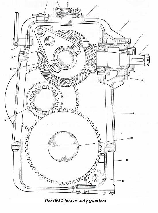
The beauty of the RF11 lies in its accessibility - for a problem with the top shaft, the top of the casing comes off - to take the axle out for reprofiling, the upper 2/3 of the box can be left in the loco by removing the bottom. In addition, the RF11 incorporates an oil pump which creates a positive oil flow to lubricate the gears in motion, and a manual handle and locking peg so that the loco can be towed with the transmission dis-engaged.
The RF11, by having two different input/crown wheel ratios and a number of top-shaft to intermediate shaft combinations, had a wide range of potential ratios to suit a loco for different duties. The most common was 12.4:1, but standard boxes came up to 6:1 and Z'ed up to 15.32:1.
Thomas Hill and Sentinel were almost exclusive SCG customers, but RF11s were also used by Yorkshire, Barclays, Drewry, English Electric (Stephenson), Bagnall, etc.
SCG also produced a smaller version of the RF11, the RF25, used in a lot of smaller Thomas Hill locos ("Noddy's") which was approximately 2/3 the size of the RF11 and only available in a standard form.
Hunslet "350"
Hunslet had their own gear-making machinery and having made their own fully-mechanical transmissions, continued to make their own final drives through to the late 1980s. The most common gearbox, the "350" could be axle or jackshaft mounted and was of similar layout in gear form to the RF11 but otherwise is very different. For starters, the casing splits vertically, so any heavy attention it requires necessitates taking the gearbox out of the loco and laying it down. The gears are straight cut and splash lubricated, so additional thin trays are incorporated to 'catch' the oil and direct it to the gear trains and bearings. Finally, whereas on an RF11 the gears are operated by internal air cylinders where the air is held "on" to hold the gearbox in mesh, the Hunslet uses an external cylinder with separate latching pistons which engage with grooves in the selector shaft, i.e. once a direction is engaged the air is (must be) turned off to the operating cylinder else the gearbox becomes pressurised and pumps the oil out. Reversing the box requires that the latching piston is first raised by its cylinder and then the selector shaft moved across.
The most common 350 ratio is 14.42:1.
Hunslet made a number of other final drives - the "600" in some 60Ton class locos, and the "650" (solely for the BR class 14s) - but the "350" is the most common in 0-4-0 and 0-6-0 standard gauge locos
Wiseman RLGB series
Alfred Wiseman, a major gear specialist, made a number of locomotive final drives under the 'RLGB' suffix (reversing locomotive gearbox) with a two-digit prefix indicating the size of the unit, in construction and appearance very similar to the RF11. Not as common as either of the above types, they were utilised in locos by Barclays, Bagnall, Clayton and Baguley.
Rolls-Royce CGF610
Rolls-Royce's erstwhile Rail Traction Department at Shrewsbury, although using RF11 gearboxes on the Sentinel range and Wiseman boxes on Steelman, nonetheless designed their own final drive gearboxes as part of their long-term plans for developing the business. A CGF310 gearbox was a 3.5:1 final drive for DMU applications, but the CGF610 was a really heavy-duty loco gearbox intended to be used where the RF11 had insufficient strength. Only a small number were built, ironically not in a Sentinel locomotive but in Yorkshire locos starting with the "Taurus"/"Indus" designs for which it was probably developed. (Taurus, trialled but not bought by BR, was an 0-8-0DH with two R-R C8 engines, for which one was used during shunting and the second brought in to boost the total horsepower to trip. In performance, it was similar to the Class 14 and probably of similar price, but aside from Western Region no BR region saw a need for this type of loco and as Taurus was trialled on Eastern Region, nothing developed. Taurus was only built for export. "Indus", the industrial version, used both engines running continuously with a different driveline but the same final drive, only 2 were built.)
Other locomotive manufacturers own
Aside from Hunslet, latter-day Baguley locos and railcars used a simple box designed and built by Baguley, and Hudswell Clarke started manufacturing their own final drives for their 35ton 0-4-0DHs. The Yorkshire Engine Company also made their own gearbox, used for example on their industrial 0-4-0DH which was classed by BR as an "02". This box was unique in that the input shaft was not designed horizontal - rather the entire drive line was angled at about 11 degrees. Three ratios, 9.05, 11.5 and 13.2, were available.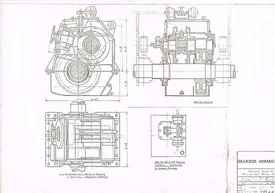
The Yorkshire final drive, as employed on the 02s
{slider title="Why does an industrial loco overheat at speed?" class="blue"} Or why does an industrial loco with a Twin Disc torque converter overheat when I try to run it at full speed?
As we have explained in another FAQ, the efficiency curve of a Twin Disc converter is at its best when in the mid-engine range (typically about 1400-1600rpm) and is then only 80%. In other words, if we apply full engine power into the converter (say 300) 20% of the input power (300/5 or 60hp) is rejected as heat. This heat must be dissipated through the cooling system - the shaft seals on a Twin Disc are carbon and will fail if cooked, quite apart from any potential fire risk.
The converter has a charge pump, whose function is to maintain a base pressure in the converter, typically 40-60psi, though it will generally work well provided there is some base pressure. The converter then ejects fluid to a cooler and having passed through the cooler, the fluid returns to the converter. A temperature switch or switches are located on the converter output line. At the highest point of the cooler is a tapping, which bleeds a small amount of fluid out of the circuit and returns it to the tank, but on the way passes through a restrictor known as an 'orifice' which looks at first like a peculiar pipe fitting. Strip it and you'll find the orifice has a protective gauze filter to prevent it from becoming blocked. (Inspect this filter from time to time - particles of metal may indicate wear/damage in the converter.)
OK, that's the basic system. On most locos the cooler is linked to the engine coolant - the heat in the converter is transferred to the engine radiator and out through the main radiator/fan. There is generally more heat coming from the converter than from the engine! (We have seen misguided people fit much smaller lorry radiators in place of genuine loco radiators and wonder why it doesn't work!) On such systems, the converter and engine temperatures move up pretty well in synch - they're bound to because if the engine temp is higher than the converter temp, the engine will transfer heat back into the converter circuit.
So imagine, you are pushing your loco to run at about 20mph on level track. Your engine speed is at full (1800-2100), the converter rpm ditto, the efficiency of the converter is well down towards zero (i.e. most input hp is being rejected,) and over 50 gallons per minute of fluid is whizzing around the converter circuit, with frictional heat adding to the problem. Unfortunately, the converter is already warm and as the heat rejection is now greater than the abilities of the cooler and radiator to cope, the converter temperature starts to rise. (The direction of travel may have an influence, too, is the rad fan blowing with or against the direction of airflow?) Actually, the worst case is when you are running downhill with a train behind you! The input hp is now coming from the train pushing, but you the driver have throttled back, slowing the engine fan and the water pump and so preventing the cooling system from removing as much heat as it could.
There are ways around this, and having had 30 years of extensive experience, Andrew's father is willing to assist - contact him via his website.
{slider title="Why don't you rebuild the class 14 back to original, with the proper Paxman engine?" title class="blue"} This is an interesting moral question that stretches far beyond the simplicity of the question and reflects the background experience of Andrew and his father.
There are some locos in the collection – such as “Grace” (the last s.g. Loco built by Hudswell Clarke) and "Coronation" the first diesel-hydraulic built by NB and the oldest s.g DH in the UK - which Andrew regards as having historic significance and will not, therefore, be materially changed.
However, for others, the idea of returning a loco to its "original" presumes that the original condition is the only form in which the locomotive could exist, or that it in some way is the only "ideal" condition. The history of locomotion is littered with designs that were not right the first time and modified and improved as new ideas, technologies or components became available.
The Class 14 901 (originally D9524) had already been repowered once in the industry (its current Rolls-Royce is its third prime mover) and returning it to “original” is neither practically nor financially worthwhile. (It would mean sourcing an obsolete engine, rewiring the locomotive to 110V, new exhaust and air intake systems, re-made plumbing and opening up the Voith to de-gear it back from 1800 to 1500rpm - all of which would just make it "the same" as all the other Class 14s in preservation.) Similarly, Andrew always took the view that any further Class 14 that came his way would be considered on its merits - if complete or nearly so, then the Paxman and 110V systems would be retained. When he was offered D9500 in the summer of 2010 he thought long and hard. The engine was stripped, there were no exhausters, and various other bits were missing but he knew that for too many enthusiasts, re-vamping the "prototype" Class 14 would be sacrilege. Nevertheless, scrapping it would have been an even bigger shame and without a doubt that was the alternative fate for the loco.
Similarly, the class 03, bought with the remains of a Deutz air-cooled engine and hydrostatic link installed, was not refitted with Gardner and fluid coupling but has been retro-fitted with a Cummins and 2-speed Twin Disc hydraulic transmission to be a more practical return to running order.
"Mainline" locomotives were generally treated as a "class" and modifications were therefore carried out on all examples and fully documented - but on the industrial market many locos were built as "one-offs" from basic designs and individual owners might choose to modify their loco to suit their requirements. For example, few industrials were built with any form of train braking, but as roller-bearing'd stock became the norm many were retrofitted with train braking for safety and practicality. Take "Cheedale" as an example. The standard Thomas Hill design had a planned space at the front of the casings so that the customer could have either a train air compressor or vacuum brake exhauster combined with the Rolls-Royce C6 engine, OR the C8 (8-cylinder) engine. Examples with the 8-cylinder engine were built for Shell and the 6-cylinder for the MoD (who later came back and asked for an additional train air compressor which was retro-fitted in front of the radiator as it was not originally called for. ICI came and asked for everything the 8-cylinder engine, exhauster and compressor, resulting in a loco with an extended casing but still immediately recognisable as a Thomas Hill chain drive Vanguard.
Those alterations were performed by the original manufacturer, but Andrew's 03 is also a case in point. Not only was it re-powered on site in Belgium but - presumably because the owner was unaware of what weight the loco ought to be or the implications of increasing weight on to axles and springs - roughly 10tons of steel slab was added to the loco, scaling it at just under 38tons
Moreover, the vast majority of industrial locos were not - in this country - expected to do "tripping" duties. Most industrial sites were closely connected to the national network and the typical industrial probably averaged only a walking pace through its working day. Indeed, from a safety point of view, some industrial operators would not want their locomotives able to travel at speeds which, within the factory/quarry/mill/sidings would be dangerous.
But when put in a heritage railway environment operators seem surprised to find that the loco won't do 25mph without overheating the transmission, and often such locomotives are casually dismissed as a result. Of course, they were not built with that sort of work in mind, and if they are to earn their keep it is not unreasonable that alterations be made to suit, and in many respects, this is in keeping with the philosophies of their original manufacturers and owners. {/sliders}